ADXRS290’s First Words
GSoC 2020 [ 0x04 ]
14 Jul 2020There are a few more things to cook after our silhouette driver to attain a cheerful face from a successful probe test. We’ll attempt a OF style match of our ADXRS290 device with the skeleton driver, i.e. by creating a device-tree overlay. Configuring our kernel so as to build the drivers/iio/gyro/adxrs290.c module, statically or dynamically, will be explored too. Additionally, kernel practices such as on how to fill the MAINTAINERS document for the automated process of mailing a patch to the maintainers of a driver upstream using ./scripts/get_maintainer.pl, how to create a binding document for the device-tree overlay file, etc. will be covered in this tutorial.
My plan is to NOT spoon-feed you with the how device-tree overlays work (simply because there are many resources authored by experts with much more experience I possess); so like always, I’ll leave you with what I consider good resources to get started and take you through ADXRS290’s overlay as an example.
Device Tree Resources:
- “Device Tree For Dummies” by Thomas Petazzoni at ELC 2013 - Video & Slides
- “Device Tree, overlays, and parameters” - Raspberry Pi Documentation - Document
- “Device Tree Overlay Notes” - Linux kernel Documentation - Document
- “The DeviceTree Specification” - devicetree.org - Link
Perfect, I shall now go ahead assuming you’re familiar with device-trees. Also, before getting started with writing your own overlay its a good idea (at least for me) to refer to overlays already accepted and in the kernel.
(Disclaimer: SPI master == SPI producer, SPI slave == SPI consumer (owing to recent events))
My overlay fragment was to come under the root node (/) with a target SPI controller. In my case, amongst the 3 SPI controllers, I chose the main SPI controller - SPI0 - which has two chip selects, since its interfacing pins are exposed on all RPi headers. More on these controllers, the main controller (SPI0) and the auxiliary ones (SPI{1, 2}), can be found in BCM2837 ARM Peripherals datasheet. So, as I mentioned, my target SPI producer node is the one with an alias “spi0” (alias for spi@7e204000). Now, under this target node, I define my overlay. In this overlay, firstly, I make sure the SPI producer has properties: #address-cells = <1> and #size-cells = <0>; this tells the SPI producer to expect a single address with no length when declaring the address space of the consumer device using reg property. More on reg later, when declaring the properties for our consumer device. Now, in the SPI producer node, the last thing we make sure is for the producer to be enabled! We do that with status = "okay"; which is the default value of the property; status = "disabled", being a no-brainer, disables SPI0.
Now, we define our SPI consumer node, adxrs290@0. adxrs290 is the node and 0 signifies the address space it lives in (you’ll understand that once we define the reg property). The compatible property is what is looked in the “database” for a “compatible” driver. The convention is to prefix the manufacturer’s name to the chip’s/device’s name. So, for us, compatible = "adi,adxrs290" - the driver core will now handle matching this device to a driver which if you remember has the exact same “compatible” string. Moving ahead, in the case of SPI, reg property signifies the chip select number of the SPI consumer device. So, with reg = <0>, my device is expected to be interfaced at spi0.0. Another required property to be included is the spi-max-frequency which I hope needs no explanation on what it means. The value of it must be searched for in the datasheet of the specific device; for ADXRS290: spi-max-frequency = <5000000> (5MHz).
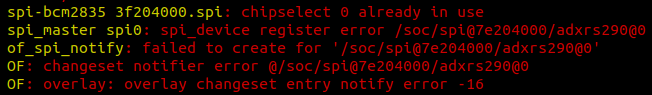
Another crucial thing to define in the overlay file is the disabling of another SPI consumer device, ‘spidev0’, which depending upon your loaded device-tree could be the attached to spi0.0, marking it busy. If its not disabled, kernel message buffers (examine using dmesg -w) may output such an error:
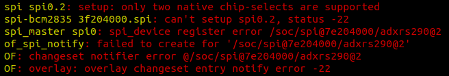
Another workaround for this (if you don’t feel comfortable disabling ‘spidev0’) is to initialise a third chipselect and then tell the adxrs290 child node to use it using reg = <2>. See arch/arm/boot/dts/overlays/spi1-3cs-overlay.dts in ADI’s tree to see how you can attach a certain GPIO function (in this case to act as a CS line) to a GPIO pin. I didn’t investigate much along this path after it produced me an error (attached below) and hence decided to go with the first, easier method of disabling ‘spidev0’.
What my dt-overlay finally looks like:
# arch/arm/boot/dts/overlays/rpi-adxrs290-overlay.dts

/dts-v1/;
/plugin/;

/ {
	compatible = "brcm,bcm2835";

	fragment@0 {
		target = <&spidev0>;

		__overlay__ {
			status = "disabled";
		};
	};

	fragment@1 {
		target = <&spi0>;

		__overlay__ {
			#address-cells = <1>;
			#size-cells = <0>;
			status = "okay";

			adxrs290@0 {
				compatible = "adi,adxrs290";
				reg = <0>;
				spi-max-frequency = <5000000>;
			};
		};
	};
};
Make sure while building the kernel and compiling the overlays, the build process also compiles our dts file into dtbo by appending rpi-adxrs290.dtbo to the list of targets in arch/arm/boot/dts/overlays/Makefile (which is called recursively from the top-level Makefile) in lexicographic order (kernel devs are very particular about this). See my commit, in case these words don’t register with you.
Device-tree binding’s raison d’etre is to act like a human-readable document which manifests how a hardware device is described. Quoting Marta Rybczynska from the article “Device-tree schemas” on LWN.net:
“The device-tree bindings define how a particular piece of hardware is described in a device tree. Drivers then implement those bindings. The device-tree documentation shows how to use the bindings to describe systems: which properties are available and which values they may have. In theory, the bindings, drivers and documentation should be consistent with each other. In practice, they are often not consistent and, even when they are, using those bindings correctly in actual device trees is not a trivial task. As a result, developers have been considering formal validation for device-tree files for years.”
This is where Rob Herring’s proposal to validate device-tree files in an automated manner using an existent (shutting the need of coming up with a new language and tools around it) schema vocabulary (JSON). The efforts of converting the prevailing binding documents in .txt to .yaml are ongoing - I encourage you to contribute for the same!
Do you realise how the flow of the tutorials (skeleton driver -> device-tree -> dt-binding) is contradictory to the purpose of dt-bindings?! Well, I didn’t think such a flow would be destructive in such “small-scaled” projects and trivial devices (ergo trivial device-trees) but when things scale up, its better to go with Marta’s flow (device-tree -> dt-binding -> skeleton driver), I suppose.
Study how binding documents are to be created for a specific device-tree and validate those with tools available. What the binding document for ADXRS290 looks like:
# Documentation/devicetree/bindings/iio/gyroscope/adi,adxrs290.yaml

# SPDX-License-Identifier: (GPL-2.0 OR BSD-2-Clause)
# Copyright 2020 Analog Devices Inc.
%YAML 1.2
---
$id: http://devicetree.org/schemas/iio/gyroscope/adi,adxrs290.yaml#
$schema: http://devicetree.org/meta-schemas/core.yaml#

title: Analog Devices ADXRS290 Dual-Axis MEMS Gyroscope

maintainers:
  - Nishant Malpani <nish.malpani25@gmail.com>

description: |
  Bindings for the Analog Devices ADXRS290 dual-axis MEMS gyroscope device.
  https://www.analog.com/media/en/technical-documentation/data-sheets/ADXRS290.pdf
properties:
  compatible:
    enum:
      - adi,adxrs290

  reg:
    maxItems: 1

required:
  - compatible
  - reg

examples:
  - |
    spi {
        #address-cells = <1>;
        #size-cells = <0>;
        adxrs290@0 {
                   compatible = "adi,adxrs290";
                   reg = <0>;
                   spi-max-frequency = <5000000>;
        };
    };
...
One of the best things about the Linux kernel lies in the principle of modularity and configuration of the kernel for one’s own demands or use-cases. The Kbuild system beautifully realises this. So, for developers/users to be able to use our driver, we must give birth to a CONFIG symbol which once selected builds our kernel module. This is done in the directory-level (drivers/iio/gyro, in our case) Kconfig file:
# drivers/iio/gyro/Kconfig

config ADXRS290
tristate "Analog Devices ADXRS290 Dual-Axis MEMS Gyroscope SPI driver"
depends on SPI
help
  Say yes here to build support for Analog Devices ADXRS290 programmable
  digital output gyroscope.

  This driver can also be built as a module. If so, the module will be
  called adxrs290.
The CONFIG symbol, CONFIG_ADXRS290, can now be reported under the build process specifying how to compile the module associated with the symbol. This is a one-liner (again, append it in lexicographic order):
# drivers/iio/gyro/Makefile

obj-$(CONFIG_ADXRS290) += adxrs290.o
Now, if I introduce CONFIG_ADXRS290=y (static module) or CONFIG_ADXRS290=m (dynamic module) to my .config file (by doing a make menuconfig and searching for the corresponding CONFIG symbol), the Kbuild system knows how to compile my adxrs290.c kernel module. Neat!
Marcelo Schmitt (GSoC’19 @ The Linux Foundation) has a brilliant article on “Raspberry Pi kernel compilation” which explains in quite intricate detail, how Kbuild and these config symbols work. Linux Journal’s article on “Kbuild: the Linux Kernel Build System” is definitely another good source.
After all this, the MAINTAINERS document should be updated to track maintainers of a kernel driver so that people know whom to reach to in case patches are to be sent for that driver. Please read the instructions in the beginning of the document to comply with the standards and not make a mess. In my case, it looks something like this:
# MAINTAINERS

ANALOG DEVICES INC ADXRS290 DRIVER
M:	Nishant Malpani <nish.malpani25@gmail.com>
L:	linux-iio@vger.kernel.org
S:	Supported
F:	drivers/iio/gyro/adxrs290.c
F:	Documentation/devicetree/bindings/iio/gyroscope/adi,adxrs290.yaml
I pretty much religiously follow Marcelo’s tutorial from this point on - on how to compile the kernel for Raspberry Pi (3B+) but I’ll still document the process here, in a succint manner possible. But I still recommend reading Marcelo’s tutorial once as explains in complete detail.
Instead of doing a make menuconfig as I mentioned earlier, I use ADI’s custom defconfig (can be found in their tree): adi_bcm2709_defconfig (and make sure you add your CONFIG symbol as I did here). So, simply do:
make ARCH=arm adi_bcm2709_defconfig
Then, assuming you have a cross-compiler toolchain (see Marcelo’s tutorial on how to download one), do:
sudo ARCH=arm CROSS_COMPILE=../gcc-linaro-7.4.1-2019.02-x86_64_arm-linux-gnueabi/bin/arm-linux-gnueabi- make zImage modules dtbs -j8
Plug in the prepared SD card (check out my tutorial on “burning” ADI’s Kuiper OS image, if you haven’t) and now simply copy the compiled kernel & the compiled dtbs and the install modules in the appropriate place. I wrote a script to do the same (yet to add features to backup the existing kernel in case things go down south):
#! /bin/bash

BOOT_DIR="/media/laymanish/boot"
ROOT_DIR="/media/laymanish/rootfs"
KERNEL_SRC_DIR="/home/laymanish/git/kernels/linux"
KERNEL_BUILT_DIR="${KERNEL_SRC_DIR}/arch/arm/boot"

if [[ ! -d $BOOT_DIR ]]; then
	echo "boot mount not found!"
	exit 1
fi

if [[ ! -d $ROOT_DIR ]]; then
	echo "root mount not found!"
	exit 1
fi

echo "Writing the kernel and the dtbs to the SD card..."
cp ${KERNEL_BUILT_DIR}/zImage ${BOOT_DIR}/kernel7.img
cp ${KERNEL_BUILT_DIR}/dts/*.dtb ${BOOT_DIR}/
cp ${KERNEL_BUILT_DIR}/dts/overlays/*.dtbo ${BOOT_DIR}/overlays/

echo "Installing kernel modules..."
cd $KERNEL_SRC_DIR
sudo make INSTALL_MOD_PATH=$ROOT_DIR modules_install

sleep 2

echo "Syncing the write buffers..."
rsync $BOOT_DIR/
rsync $ROOT_DIR/

sleep 2

echo "umounting..."
sudo umount $BOOT_DIR
sudo umount $ROOT_DIR
Upon booting into RPi, enable loading of the overlay we defined at boot-time, in /boot/config.txt (reboot once changes are made):
# /boot/config.txt

dtoverlay=rpi-adxrs290
This can be done with dtoverlay command-line utility too but its too tedious to do it everytime.
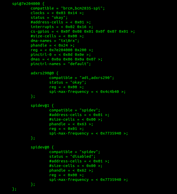
A good test to see the live kernel tree is using the device-tree compiler (dtc) (see command below) or perhaps explore the sysfs file system (see /sys/firmware/devicetree/base).
$ dtc -I fs -O dts /proc/device-tree/
If you run the above command, you should be able to see our overlayed portion under spi@7e204000 child node, as seen in the picture below:
Time to “see” ADXRS290’s first words. Remember in the skeleton driver, we’ve added a greeting print message in adxrs290_probe() callback. So, we should expect to see that once we load our kernel module (if built dynamically) in the kernel message buffer.
$ lsmod | grep adxrs290
>
$ sudo modprobe -v adxrs290
> insmod /lib/modules/4.19.86-v7+/kernel/drivers/iio/gyro/adxrs290.ko
$ lsmod | grep adxrs290
> adxrs290		16384 0
The above shows the module has been successfully loaded.
To know more about the kernel module, do a naive modinfo which is filled with the meta-data we filled while constructing the skeleton driver and many other valuable information (vermagic!):
$ modinfo adxrs290
> filename:       /lib/modules/4.19.86-v7+/kernel/drivers/iio/gyro/adxrs290.ko
license:        GPL
description:    Analog Devices ADXRS290 Gyroscope SPI driver
author:         Nishant Malpani <nish.malpani25@gmail.com>
srcversion:     8860700E1CF1EE7564DE47A
alias:          of:N*T*Cadi,adxrs290C*
alias:          of:N*T*Cadi,adxrs290
depends:
intree:         Y
name:           adxrs290
vermagic:       4.19.86-v7+ SMP mod_unload modversions ARMv7 p2v8
On a successful probe, dmesg should show (beware of your kernel log levels):
$ dmesg
>
[...]
adxrs290: Hello from the probe side
[...]
GG! Such lovely words.